How Are Rigid Flex Rigid PCBs Different From Rigid PCBs?
Rigid Flex Rigid PCBs Different From Rigid PCBs
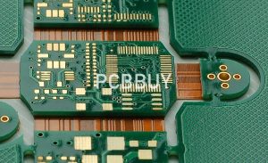
Rigid flex rigid pcbs are a hybrid circuit board that combines the best of both rigid and flexible PCBs. They are used in applications that demand both a high level of reliability and the ability to bend and fold for space efficiency. These circuit boards are often seen in aerospace and military applications, as well as medical devices. They can also be found in industrial equipment, automotive electronics and other electronic devices that need a combination of flexibility and reliability.
Rigid flex PCBs are designed to withstand repeated bending and folding without losing structural integrity or functionality. This enables them to meet the demands of applications in high vibration environments where mechanical stress can damage other types of circuit boards. To overcome this challenge, manufacturers implement specific design and manufacturing considerations, such as adding stiffeners to specified areas of the circuit. These stiffeners are made of rigid material like FR4 and help stabilize the flexible sections of the board.
In addition to providing strength, stiffeners can improve electrical performance by reducing impedance mismatches. They can also prevent signals from bouncing around the flexible section of the circuit, which would otherwise interfere with the performance of the entire board. They can also reduce assembly time by replacing multiple FR4 PCBs and cables with a single rigid-flex circuit.
Another important consideration is the rigid flex rigid pcb ability to handle thermal expansion and contraction. This is especially crucial for applications that operate in high-temperature environments. By using materials with low coefficients of thermal expansion and implementing heat sinks, rigid-flex circuits can mitigate thermal stresses that may cause structural failures.
How Are Rigid Flex Rigid PCBs Different From Rigid PCBs?
A rigid-flex circuit’s thickness is also an important factor to consider when designing for bending and folding. By utilizing thin copper traces with wide ends, you can increase the stiffness of the circuit, which will improve its mechanical performance and resistance to bending and flexing. This will also make it easier to solder the traces, as you can avoid making them too small or placing them close together.
In addition, a thicker board can be stronger in the face of mechanical stress, which is essential for applications that will see frequent use or harsh environmental conditions. However, you should remember that the increased thickness can impact signal propagation. Therefore, you should plan your layer count and copper thickness to optimize the signal path while maintaining adequate rigidity.
Other critical design factors include the ability to withstand vibration and the need for strong, reliable connections between rigid and flexible sections. This can be achieved by ensuring that signal layers have proper transitions between the rigid and flexible sections. Misalignment of signals can lead to impedance problems and signal degradation, which can be difficult to fix once the rigid-flex circuit is assembled.
Lastly, you should always ensure that your rigid-flex design is compliant with IPC-A-610 standards for mechanical and electrical specifications. This will ensure that your circuit board is up to your specific application’s requirements. If your project requires a simple design that does not require the benefits of flexi-rigid PCBs, alternatives like traditional rigid PCBs and fully flexible circuits can be more cost-effective. If you are working with a limited budget, it is important to carefully evaluate your design and choose the most appropriate options for your specific needs.